FAQ - Frequently Asked Questions
- FAQ 000: PIC is not recognized or programming fails with verify errors.
- FAQ 001: PIC is not deteced when using JDM programmer.
- FAQ 002: PICPgm reports "System Error: Unable to open LPT port driver portio.sys"
- FAQ 003: Could PICPgm be integrated into my IDE?"
- FAQ 004: How to add a new programmer to PICPgm?"
- FAQ 005: LVP programmer works with 16Fxxx PICs, but does not detect 18Fxxxx PICs?
- FAQ 006: PIC cannot be programmed in High Voltage Mode (High Voltage Programmer)!
- FAQ 007: Why can 10Fxxx PICs (and some other devices) not be autodetected?
- FAQ 008: Is it possible to use JDM programmer with USB to COM port converter?
- FAQ 009: I get the following error: Verify Error: Cfg Mem 0x000006: PIC=0x0085 Buf=0x0081!
- FAQ 010: How do I set OSCCAL with the command line version of PICPgm?
- FAQ 011: How can I read the OSCCAL value?
FAQ 000: PIC is not recognized or programming fails with verify errors.
There are several possible reasons for this. Please check the points mentioned in the troubleshooting guide.
FAQ 001: PIC is not deteced when using JDM programmer.
Due to the original JDM programmer can not control the supply
voltage, there is a problem with some of the new PIC's, eg PIC12F675,
12F629, and some others with an internal oscillator.
To overcome this problem, the JDM programmer has to be modified slightly.
A detailed schematic of the modification can be found in the
Hardware
section.
For more details regarding the problem refer to
http://users.tpg.com.au/btkelly/jdm_b.htm
FAQ 002: PICPgm reports "System Error: Unable to open LPT port driver portio.sys"
PICPgm needs the portio.sys driver to be able to access the parallel port (LPT)
under Windows NT/2k/XP. The driver is automatically installed upon start
of the program.
If you do not have administrativ rights on your PC, PICPgm fails to install
the driver and reports the error.
FAQ 003: Could PICPgm be integrated into my IDE?
Yes, PICPgm can easily be integrated into your IDE. An example of how to integrate PICPgm into CCS IDE or Windows Explorer can be found in the Software section.
FAQ 004: How to add a new programmer to PICPgm?
PICPgm gets the information about the supported programmer out of the file "pgmifcfg.xml". This file is located in the PICPgm installation directory. To add a new programmer just open the file with a text editor. There you will find sections like the following:
<PgmIf name="User Defined Programmer" typ="HVP" connection="LPT">
<PinCfg name="MCLR" pin="5" invert="0" />
<PinCfg name="PGM" pin="4" invert="1" />
<PinCfg name="CLK" pin="3" invert="1" />
<PinCfg name="DOUT" pin="2" invert="1" />
<PinCfg name="DIN" pin="10" invert="1" />
</PgmIf>
Copy this section and paste it at the end of the file (but before the </Config> tag). Change the attributes of the XML tags to fit to you hardware.
The <PgmIf> tag defines basic settings of the programmer. It has the following attributes:
- name: name of the PIC programmer; e.g. name="My Programmer"
- typ: specifies if the programmer is a High Voltage Programmer ("HVP") or Low Voltage programmer ("LVP")
- connection: connection of the programmer; allowed values: COM, LPT or USB
The <PinCfg> tag defines the pin configuration for each programmer signal. It has the following attributes:
- name: name of the pin, must not be changed.
- pin: defines the pin name which the programmer signal is associatet to.
For LPT programmers the pin numbers have to be given according to the 25-pole Sub-D LPT connector.
For COM programmers the pin numbers have to be given for the 9-pole Sub-D connector.
For USB programmers with FT245 chip the pin is associated to the data ports of the chip, i.e. 0 equals D0, 1 equals D1, ..., 7 equals D7. Please note that D6 and D7 are used internaly and shall not be used for other purposes! - invert: invert the output/input signal (e.g. needed if inverter is used).
NOTE: PGM is used for different things depending on the programmer type. For Low voltage programmers PGM is used to control the PGM pin (e.g RB3, RB5). For High voltage programmers PGM controls Vdd.
FAQ 005: LVP programmer works with 16Fxxx PICs, but does not detect 18Fxxxx PICs?
I made your low voltage icsp programmer, and tested it with a 16F877A, and it was able to detect it just fine, however it did not detect a 18F4455, no matter what I tried. So after much reading and testing, I came across http://www.qsl.net/dl4yhf/winpic/index.htm#pgd_pgc_filtering So I tried adding the two caps, I used a 15pf from PGD & PGC to gnd, and that did the trick - it detected the device first time.
FAQ 006: PIC cannot be programmed in High Voltage Mode (High Voltage Programmer)!
PICs which can be programmed either in High Voltage Mode or Low Voltage Mode may make problems
during programming in High Voltage Mode if the LVP bit in the configuration memory is enabled.
This problem especially occurs if the MCLR pin is used as I/O pin. In this case the PGM pin
should be tied to GND.
Here's what the programming specification says: "If the LVP fuse is enabled,
PGM should be held low to prevent inadvertent
entry into LVP mode."
I found this problem with a PIC 16F628A where the MCLR pin was configured as I/O pin and the LVP
bit in the configuration memory was 1 (Low Voltage programmin enabled). If the PGM pin of the PIC
was floating, programming was not possible (or only sporadically). After connection the PGM pin
(RB4 on 16F628A) to GND, everything worked fine!
FAQ 007: Why can 10Fxxx PICs (and some other devices) not be autodetected?
The autodetection algorithm is based on the unique device ID which is stored in the PIC.
The 10Fxxx PICs (and some ohter PICs too) don't have a device ID an hence cannot be detected
automatically. To find out which PIC can be autodetected just check the list in the
Supported Devices
section.
To program PICs which have no device ID the PIC typ has to be selected manually with the
combo box in the toolbar.
FAQ 008: Is it possible to use JDM programmer with USB to COM port converter?
Unfortunately, the JDM programmer does not work with a USB to COM port converter.
Background: The JDM doesn't actually use the serial port as other applications would do. It just uses some of the handshake lines to generate the necessary programming timing, so it is no "usual" COM port communiction. Further, a USB/Serial converter isn't likely to even produce the correct voltages.
FAQ 009: I get the following error: Verify Error: Cfg Mem 0x000006: PIC=0x0085 Buf=0x0081!
This problem can occur for PIC18Fxxx devices which can be programmed in either Low-Voltage or High-Voltage mode if they are programmed with a Low-Voltage programmer.
The bit for which the verification fails here is the "LVP" configuration bit:
LVP: Low-Voltage Programming Enable bit
- 1 = Low-Voltage Programming enabled, RB5 is the PGM pin
- 0 = Low-Voltage Programming disabled, RB5 is an I/O pin
The verify error occurs since the LVP bit in the programmer buffer is 0, but in the PIC the LVP bit is 1.
Reason for the problem: The LVP bit can only be set to 0 if the PIC is programmed in High-Voltage mode.
If you do not need RB5 as I/O pin and RB5 is held on GND level you can ignore this verify error. It will not cause any problems.
Here an extract of the PIC datasheet regarding the LVP bit:
The LVP bit in Configuration register, CONFIG4L, enables Single-Supply (Low-Voltage) ICSP Programming. The LVP bit defaults to a 1 (enabled) from the factory. If Single-Supply Programming mode is not used, the LVP bit can be programmed to a 0 and RB5/PGM becomes a digital I/O pin. However, the LVP bit may only be programmed by entering the High-Voltage ICSP mode, where MCLR/VPP/RE3 is raised to VIHH. Once the LVP bit is programmed to a 0, only the High-Voltage ICSP mode is available and only the High-Voltage ICSP mode can be used to program the device.
Note 1: The High-Voltage ICSP mode is always available, regardless of the state of the LVP bit, by applying VIHH to the MCLR/ VPP/RE3 pin. 2: While in Low-Voltage ICSP mode, the RB5 pin can no longer be used as a general purpose I/O.
FAQ 010: How do I set OSCCAL with the command line version of PICPgm?
To set OSCCAL (oscillator calibration) use the command line option "-osccal" (or "-osccalbak" for the backup location of OSCCAL). Usually, there is no need for the user to modify the OSCCAL because PICPgm takes care that OSCCAL is getting restored after erasing the PIC. But if the OSCCAL value got lost due to some reason it can be used to restored the OSCCAL value.
Please note that OSCCAL can only be modified along with a programming or erase operation!
Example:
Set OSCCAL during programming:
picpgm -p test.hex -osccal 0x342c
Set OSCCAL during bulk erase:
picpgm -e -osccal 0x342c
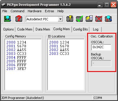
In the GUI version of PICPgm the OSCCAL (and OSCCAL Backup if supported) can be modified in the configuration memory tab:
FAQ 010: How can I read the OSCCAL value?
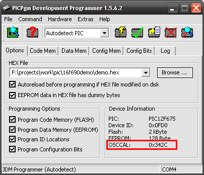
PICPgm will display some common information regarding the PIC conntected to the programmer during every operation. One of the information provided here is the OSCCAL value which was found in the PIC. Please note that not all PICs have an OSCCAL configuration!
In the GUI version of PICPgm you can find the OSCCAL value here:
In the command line version of PICPgm you can e.g. use picpgm -p to report all details of the connected PIC. One of the information which is provided is the OSCCAL value (but only if PIC supports OSCCAL!).
E.g.:
c:\picpgm\>picpgm -r
PIC Development Programmer Version 2.5.6.2
http://www.members.aon.at/electronics/pic/picpgm
Copyright 2002-2011 Christian Stadler (ch.stadler@gmx.at)
(built on Jun 23 2011 at 11:03:03)
==================================================================
Autodetecting Programmer ...
Programmer:  JDM Programmer
at COM4
Autodetecting PIC ...
Calibrating delay: 50us delay took 36us (loop counter=703)
PIC name:    PIC12F675
Device ID:   0x0FD0
Flash:       2 kByte
EEPROM:      128 Byte
OSCCAL:      0x342C
time 1.0 seconds!